
Mastering Modbus: Connecting 3rd-Party Devices in Mervis IDE
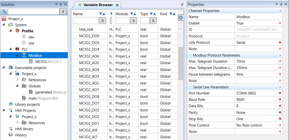
If you need to connect third-party hardware to your PLC, you will likely use the Modbus protocol driver. While integrating foreign hardware might seem intimidating, Mervis IDE breaks the process down into a few logical layers.
How Modbus is Structured in Mervis
- The Channel: This is where you specify the physical port on the PLC. For a serial line (Modbus RTU), you must ensure parameters like Baud Rate, Data Bits, Parity, and Stop bits exactly match the documentation of your 3rd party device.
- The Device: This represents the actual Modbus server (hardware) on the bus. While a bus can technically support up to 255 devices, limiting it to 60 to 80 devices makes commissioning and service much easier.
- Groups and Datapoints: To optimize bus traffic and speed up data transfer rates, Modbus communication happens in groups of datapoints. A datapoint is just a communication definition; to use it in your program, you map it to a global variable. This abstraction is highly useful: if a physical I/O module gets damaged, you can easily reconnect your variable to a different datapoint without rewriting your core program.
Pro-Tip: Adjusting Timeouts
Different devices respond at different speeds. While a 70 ms Max. Telegram Duration (timeout) works fine for standard modules, 3rd party devices like PV inverters or VSDs often require a longer span of about 200 to 500 ms.
Ready to start wiring up your hardware? Read the complete, step-by-step configuration guide in our official Knowledge Base.